Fake Fan RPM Sensor
References
[H]ard|Forum - Generate Fan RPM Signal W/O Fan
Description
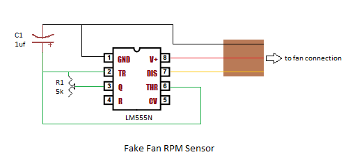
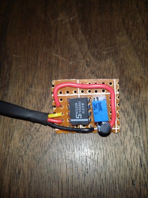
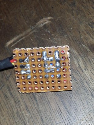
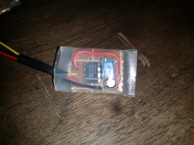
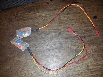
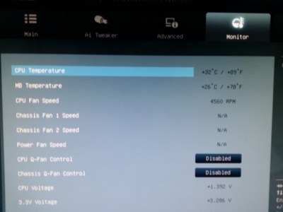
This circuit is a fake fan rpm sensor. It allows you to send fake speed information so a computer/device thinks a fan is attached and it is spinning. The speed is setable by a 5k variable resistor. I am using this with my water coooling setup to stop my bios and vmware esxi from reporting a cpu fan error (since there is no cpu fan in this setup). This circuit image on my site is a redraw of a post at "[H]ard|Forum" by "Mohonri" with a correction in the LM555N pinout. The other pictures are from the two fake fan sensors I made based on my updated diagram.
Mohonri wrote the following description for using a 555 for this application.
"tie the Threshold and Trigger pins together. Put in a capacitor between these two pins and ground. Put a resistor between the Output and these two pins.
Fans typically pull the RPM line low twice per revolution, for a quarter-revolution each time. At least, that's what I've seen when I've played with it (and yes, I have played with it). So an 8000 RPM fan will pull that line low 16,000 times per minute, or about 267 times per second. That's every 3.75ms. Now divide that by half, because the line needs to be pulled low for half the time and left floating the other half, so now you have 1.875ms. That's your time constant, and it roughly equals R * C (the resistor and capacitor's values multiplied). If you use a 1uF cap, you'll need a 1.875kOhm resistor or something close to it. Actually, on second thought, instead of using a fixed-value resistor between the output and Threshold/Trigger, use a 5k pot, and adjust it until you get exactly the frequency you need.
The last step is to tie the Discharge pin to the RPM signal, and you should be good to go."
Circuit Diagram
Finished Images
Document Actions
